Arduino board - check
Big box of components - check
Softare installed on PC - check
Ohms Law - wait a minute, who said anything about math?
Assembling circuits to pre-prepared instructions and copying code is all well and good, but the real fun (and learning) begins when deviating from the instructions. But before we can run we have to walk.
There are two main bits to working with the Arduino. The physical, 'hard', or seen elements, and then the 'soft', or unseen elements.
The physical side of things incorporate electronic circuits comprising of input devices (switches and sensors), and output devices (lights, buzzers, motors, etc). There are also lots of other bits that enable the circuit to function (resistors, capacitors, etc).
The soft side is the code (or instructions) telling the inbuilt computer on the Arduino what do do with the aforementioned input and output devices.
Fortunately there are many people who like to share their knowledge and the internet is bursting with projects and bits of code that can be borrowed from to create new things. Of course, once the skills have been acquired there is nothing stopping you from creating your own code and circuits.
I have found that a good workflow is to...
1. Draw the circuit and figure out what components will be needed.
This is where you can do some math (Ohms Law) to figure our what components will be needed.
2. Build the physical circuit.
3. Write the code.
4. Upload the code to the Arduino.
5. See if it works.
Step 1.
Draw the circuit and figure out what components I will need.
For the first test, I will not be using the micro controller part of the arduino board, just the built in power supply to light up a LED (light emitting diode). A diode is a one way gate for electricity. A LED is one that allows some of the electrical energy to be converted to light energy when the electrical current is passing through it.
The LED I have runs at 2 volts.

The power supplies that I have available are a 9 volt battery pack...

or the 5 volt power supplied by the arduino.

The arduino has the built in ability to take a variety of input power levels and still give an even 5 volt output. This means that by running everything through the arduino I can power my circuit by the 4.5v USB power that is supplied by my laptop computer, or by my 9 volt battery pack, all without having to change components in the circuit each time.
The circuit looks like this...

I know that the power supply is 5v.
I know that the LED runs at 2v.
I also know that running 5v through a 2v LED will burn it out. Bad news!
To stop the LED burning out I need to limit the power running through it.
Time for some basic math...
The power supply is 5v.
The LED is 2v.
This means that I need to drop the voltage to the LED by 3v.
I will do this with a resistor.

To figure out what type of resistor I need to use I will use Ohm's Law.
Ohm's law is a rule regarding the relationship between Voltage, Current, and Resistance.
It is not to be confused with Murphy's Law (anything that can go wrong, will go wrong), or Cole's Law (shredded cabbage with a mayonnaise dressing).

To figure out the resistance I need I divide the Voltage by the Current.
3v / 0.02 amps (or 2mA) = 150 ohms.
I don't have a 150 ohm resistor so I will round up to the nearest one which is 220 ohms.

The solved circuit looks like this...

Now that that is all over it is time to build the physical circuit.
I will do this using a breadboard, which is a handy tool for easily building circuits.
In this circuit I have also added a small push button switch.
Adding the switch gave a very important learning opportunity that I will discuss later. But for now, let's see the first circuit in action.
While the ability to regulate a power supply is pretty handy, the true power of the arduino comes from the onboard programmable computer chip (the micro controller).
Instructions can be written on a computer (code) which tells the arduino what to do with each component (switches, lights, sensors, etc). This code is then uploaded to the arduino so it can run the code without having to be connected to the main computer.
This means that my simple circuit (turning on a light at the press of a button) can now be made a little more interesting. I can change how things work by changing the code, without having to change components in the circuit each time.
Essentially I am making up a list of rules for the circuit to adhere to.
Here is an example of using a piece of code to flash two LEDs on and off.
To do this each component needs to be attached to one of the assigned 'digital' pins on the arduino board, rather than the direct power supply. This way each component and its relative pin can be identified in the code and instructions can be applied to that specific pin.
You will notice that I am still using the switch os a simple on / off device that works by allowing the electrical current to pass through when pressed. Doing it this way only enables a single function. By adding the switch as an input device (by feeding it through a digital in) and making rules in the code about what to do with it, the switch can be made a lot smarter. Rather that just turning things on and off, it can now give feedback into the code with its own rules attached.
The code tells the board what to turn on and off, and when. The 'when' can be simply "every two seconds", or "when the button is pressed" or "only after the button is pressed 5 times and the temperature sensor tells me that it is over 28 degrees celcius).
Big box of components - check
Softare installed on PC - check
Ohms Law - wait a minute, who said anything about math?
Assembling circuits to pre-prepared instructions and copying code is all well and good, but the real fun (and learning) begins when deviating from the instructions. But before we can run we have to walk.
There are two main bits to working with the Arduino. The physical, 'hard', or seen elements, and then the 'soft', or unseen elements.
The physical side of things incorporate electronic circuits comprising of input devices (switches and sensors), and output devices (lights, buzzers, motors, etc). There are also lots of other bits that enable the circuit to function (resistors, capacitors, etc).
The soft side is the code (or instructions) telling the inbuilt computer on the Arduino what do do with the aforementioned input and output devices.
Fortunately there are many people who like to share their knowledge and the internet is bursting with projects and bits of code that can be borrowed from to create new things. Of course, once the skills have been acquired there is nothing stopping you from creating your own code and circuits.
I have found that a good workflow is to...
1. Draw the circuit and figure out what components will be needed.
This is where you can do some math (Ohms Law) to figure our what components will be needed.
2. Build the physical circuit.
3. Write the code.
4. Upload the code to the Arduino.
5. See if it works.
Step 1.
Draw the circuit and figure out what components I will need.
For the first test, I will not be using the micro controller part of the arduino board, just the built in power supply to light up a LED (light emitting diode). A diode is a one way gate for electricity. A LED is one that allows some of the electrical energy to be converted to light energy when the electrical current is passing through it.
The LED I have runs at 2 volts.

The power supplies that I have available are a 9 volt battery pack...

or the 5 volt power supplied by the arduino.
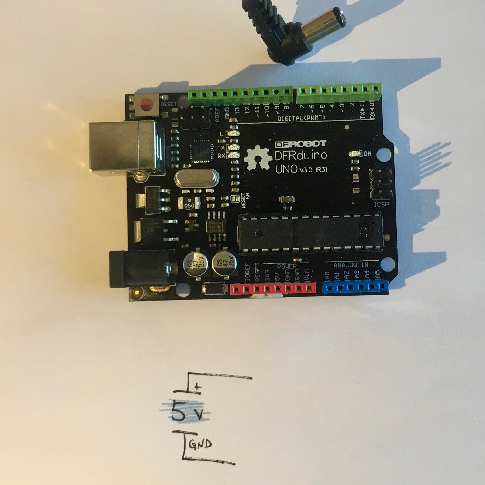
The arduino has the built in ability to take a variety of input power levels and still give an even 5 volt output. This means that by running everything through the arduino I can power my circuit by the 4.5v USB power that is supplied by my laptop computer, or by my 9 volt battery pack, all without having to change components in the circuit each time.
The circuit looks like this...

I know that the power supply is 5v.
I know that the LED runs at 2v.
I also know that running 5v through a 2v LED will burn it out. Bad news!
To stop the LED burning out I need to limit the power running through it.
Time for some basic math...
The power supply is 5v.
The LED is 2v.
This means that I need to drop the voltage to the LED by 3v.
I will do this with a resistor.

To figure out what type of resistor I need to use I will use Ohm's Law.
Ohm's law is a rule regarding the relationship between Voltage, Current, and Resistance.
It is not to be confused with Murphy's Law (anything that can go wrong, will go wrong), or Cole's Law (shredded cabbage with a mayonnaise dressing).

To figure out the resistance I need I divide the Voltage by the Current.
3v / 0.02 amps (or 2mA) = 150 ohms.
I don't have a 150 ohm resistor so I will round up to the nearest one which is 220 ohms.

The solved circuit looks like this...

Now that that is all over it is time to build the physical circuit.
I will do this using a breadboard, which is a handy tool for easily building circuits.
In this circuit I have also added a small push button switch.
Adding the switch gave a very important learning opportunity that I will discuss later. But for now, let's see the first circuit in action.
While the ability to regulate a power supply is pretty handy, the true power of the arduino comes from the onboard programmable computer chip (the micro controller).
Instructions can be written on a computer (code) which tells the arduino what to do with each component (switches, lights, sensors, etc). This code is then uploaded to the arduino so it can run the code without having to be connected to the main computer.
This means that my simple circuit (turning on a light at the press of a button) can now be made a little more interesting. I can change how things work by changing the code, without having to change components in the circuit each time.
Essentially I am making up a list of rules for the circuit to adhere to.
Here is an example of using a piece of code to flash two LEDs on and off.
To do this each component needs to be attached to one of the assigned 'digital' pins on the arduino board, rather than the direct power supply. This way each component and its relative pin can be identified in the code and instructions can be applied to that specific pin.
You will notice that I am still using the switch os a simple on / off device that works by allowing the electrical current to pass through when pressed. Doing it this way only enables a single function. By adding the switch as an input device (by feeding it through a digital in) and making rules in the code about what to do with it, the switch can be made a lot smarter. Rather that just turning things on and off, it can now give feedback into the code with its own rules attached.
The code tells the board what to turn on and off, and when. The 'when' can be simply "every two seconds", or "when the button is pressed" or "only after the button is pressed 5 times and the temperature sensor tells me that it is over 28 degrees celcius).
Comments
Post a Comment